Chapter 31 Mental Rotation of Three-Dimensional Objects Roger Shepard and Jacqueline Metzler
Human subjects are often able to determine that two two-dimensional pictures portray objects of the same three-dimensional shape even though the objects are depicted in very different orientations.
The experiment reported here was designed to measure the time that subjects require to determine such identity of shape as a function of the angular difference in the portrayed orientations of the two three-dimensional objects.This angular difference was produced either by a rigid rotation of one of two identical pictures in its own picture plane or by a much more complex, nonrigid transformation, of one of the pictures, that corresponds to a (rigid) rotation of the three-dimensional object in depth.
This reaction time is found (i) to increase linearly with the angular difference in portrayed orientation and (ii) to be no longer for a rotation in depth than for a rotation merely in the picture plane. These findings appear to place rather severe constraints on possible explanations of how subjects go about determining identity of shape of differently oriented objects. They are, however, consistent with an explanation suggested by the subjects themselves. Although introspective reports must be interpreted with caution, all subjects claimed (i) that to make the required comparison they first had to imagine one object as rotated into the same orientation as the other and that they could carry out this "mental rotation" at no greater than a certain limiting rate; and (ii) that, since they perceived the two-dimensional pictures as objects in three-dimensional space, they could imagine the rotation around whichever axis was required with equal ease.
In the experiment each of eight adult subjects was presented with 16∞ pairs of perspective line drawings. For each pair the subject was asked to pull a right-hand lever as soon as he determined that the two drawings portrayed objects that were congruent with respect to three-dimensional shape and to pull a left-hand lever as soon as he determined that the two drawings depicted objects of different three-dimensional shapes.
According to a random sequence, in half of the pairs (the "same" pairs) the two objects could be rotated into congruence with each other (as in figure 31.1, a and b), and in the other half (the "different" pairs) the two objects differed by a reflection as well as a rotation and could not be rotated into congruence (as in figure 31.1c).The choice of objects that were mirror images or "isomers" of each other for the "different" pairs was intended to prevent subjects from discovering some distinctive feature possessed by only one of the two objects and thereby reaching a decision of noncongruence without actually having to carry out any mental rotation. As a further precaution, the ten different three-dimensional objects depicted in the various perspective drawings v^ere chosen to be relatively unfamiliar and meaningless in overall threedimensional shape.
Each object consisted of ten solid cubes attached face-to-face to form a rigid armlike structure with exactly three right-angled "elbows" (see figure 31.1). The set of all ten
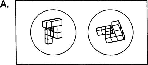
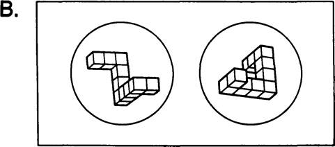
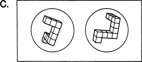
Figure 31.1
Examples of pain of perspective line drawings presented to the subjects, (a) A "same" pair, which differs by an 80o rotation in the picture plane; (b) a "same" pair, which differs by an β0o rotation in depth; and (c) a "different" pair, which cannot be brought into congruence by any rotation.
shapes included two subsets of five: within either subset no shape could be transformed into itself or any other by any reflection or rotation (short of 360o). However, each shape in either subset was the mirror image of one shape in the other subset, as required for the construction of the “different" pairs.
For each of the ten objects, 18 different perspective projections—corresponding to one complete turn around the vertical axis by 20o steps—were generated by digital computer and associated graphical output (1). Seven of the 18 perspective views of each object were then selected so as (i) to avoid any views in which some part of the object was wholly occluded by another part and yet (ii) to permit the construction of two pairs that differed in orientation by each possible angle, in 20o steps, from 0° to 180o. These 70 line drawings were then reproduced by photo-offset process and were attached to cards in pairs for presentation to the subjects.
Half of the "same" pairs (the "depth" pairs) represented two objects that differed by some multiple of a 20o rotation about a vertical axis (figure 31.1b). For each of these pairs, copies of two appropriately different perspective views were simply attached to the cards in the orientation in which they were originally generated. The other half of the "same" pairs (the "picture-plane" pairs) represented two objects that differed by some multiple of a 20o rotation in the plane of the drawings themselves (figure 31.1a). For each of these, one of the seven perspective views was selected for each object and two copies of this picture were attached to the card in appropriately different orientations. Altogether, the 1600 pairs presented to each subject included 800 "same" pairs, which consisted of 400 unique pairs (20 "depth" and 20 "picture-plane" pairs at each of the ten angular differences from 0o to 180o), each of which was presented twice. The remaining 800 pairs, randomly intermixed with these, consisted of 400 unique "different" pairs, each of which (again) was presented twice. Each of these 'different" pairs corresponded to one "same" pair (of either the "depth" or "picture-plane" variety) in which, however, one of the three-dimensional objects had been reflected about some plane in three-dimensional space.
Thus the two objects in each "different" pair differed, in general, by both a reflection and a rotation.The 1600 pairs were group into blocks of not more than 200 and presented over eight to ten 1-hour sessions (depending upon the subject). Also, although it is only of incidental interest here, each such block of presentations was either "pure," in that all pairs involved rotations of the same type ("depth" or "picture-plane"), or "mixed," in that the two types of rotation were randomly intermixed within the same block.
Each trial began with a warning tone, which was followed half a second later by the presentation of a stimulus pair and the simultaneous onset of a timer. The lever-pulling response stopped the timer, recorded the subject's reaction time and terminated the visual display. The line drawings, which averaged between 4 and 5 cm in maximum linear extent, appeared at a viewing distance of about 60 cm. They were positioned, with a center-to-center spacing that subtended a visual angle of 9o, in two circular apertures in a vertical black surface (see figure 31.1, a to c).
The subjects were instructed to respond as quickly as possible while keeping errors to a minimum. On the average only 3.2 percent of the responses were incorrect (ranging fi*om 0.6 to 5.7 percent for individual subjects). The reaction-time data presented blow include only the 96.8 percent correct responses. However, the data for the incorrect responses exhibit a similar pattern.
In figure 31.2, the overall means of the reaction times as a function of angular difference in orientation for all correct (right-hand) responses to "same" pairs are plotted separately for the pairs differing by a rotation in the picture plane (figure 31.2a) and for the pairs differing by a rotation in depth (figure 31.2b). In both cases, reaction time is
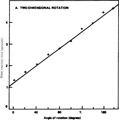
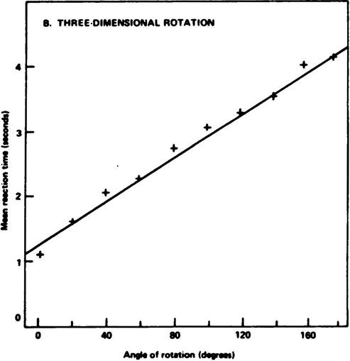
Figure 312
Mean reaction times to two perspective line drawings portraying objects of the same three-dimensional shape.
Times are plotted as a function of angular difference in portrayed orientation: (a) for pairs differing by a rotation in the picture plane only; and (b) for pairs differing by a rotation in depth.a strikingly linear function of the angular difference between the two three-dimensional objects portrayed. The mean reaction times for individual subjects increased from a value of about 1 second at 0° of rotation for all subjects to values ranging from 4 to 6 seconds at I80o of rotation, depending upon the particular individual. Moreover, despite such variations in slope, the linearity of the function is clearly evident when the data are plotted separately for individual three-dimensional objects or for individual subjects. Polynomial regression lines were computed separately for each subject under each type of rotation. In all 16 cases the functions were found to have a highly significant linear component (P <.001) when tested against deviations from linearity. No significant quadratic or higher-order effects were found (P >.05, in all cases).
The angle through which different three-dimensional shapes must be rotated to achieve congruence is not, of course, defined. Therefore, a function like those plotted in figure 31.2 cannot be constructed in any straightforward manner for the "different" pairs. The overall mean reaction time for these pairs was found, however, to be 3.8 seconds—nearly a second longer than the corresponding overall means for the "same" pairs. (In the postexperimental interview, the subjects typically reported that they attempted to rotate one end of one object into congruence with the corresponding end of the other object; they discovered that the two objects were different when, after this "rotation," the two free ends still remained noncongruent.)
Not only are the two functions shown in figure 31.2 both linear but they are very similar to each other with respect to intercept and slope. Indeed, for the larger angular differences the reaction times were, if anything, somewhat shorter for rotation in depth than for rotation in the picture plane.
However, since this small difference is either absent or reversed in four of the eight subjects, it is of doubtful significance. The determination of identity of shape may therefore be based, in both cases, upon a process of the same general kind. If we can describe this process as some sort of "mental rotation in three-dimensional space," then the slope of the obtained functions indicates that the average rate at which these particular objects can be thus "rotated" is roughly 60o per second.Of course the plotted reaction times necessarily include any times taken by the subjects to decide how to process the pictures in each presented pair as well as the time taken actually to cany out the process, once it was chosen. However, even for these highly practiced subjects, the reaction times were still linear and were no more than 20 percent lower in the "pure" blocks of presentations (in which the subjects knew both the axis and the direction of the required rotation in advance of each presentation) than in the "mixed" blocks (in which the axis of rotation was unpredictable). Tentatively, this suggests that 80 percent of a typical one of these reaction times may represent some such process as "mental rotation" itself, rather than a preliminary process of preparation or search. Nevertheless, in further research now underway, we are seeking clarification of this point and others.
References and Notes
1. Mrs. Jih-Jie Chang of the Beil Telephone Laboratories generated the 180 perspective projections for us by means of the BeU Laboratories' Stromberg-Carlson 4020 microfilm recorder and the computer program for constructing such projections developed there by A. M. NoU. See, for example, A. M. NoU, Computers Automation 14,20 (1965).
2. We thank Mrs. Chang [see (l)b and we also thank Dr. J. D. Elashoff for her suggestions concerning the statistical analyses. Assistance in the computer graphics was provided by the BeU Telephone Laboratories. Supported by NSF grant GS-2283 to R.N.S.